This example shows the procedure for using the Energy Balance features in REX. To get started, please first import the UseEnergyBalance_Example.rex file from the
Optience Corporation\REX Suite\REX Examples folder and then follow the steps below.
Step 1: Simulation with Energy Balance disabled
In the example, Temperature is selected as
Interpolated from Data in the
Reactor node. For this option, the Energy Balance is not enforced.
The model uses the Temperature values at the data points in each experimental
set to interpolate temperature throughout the reaction.
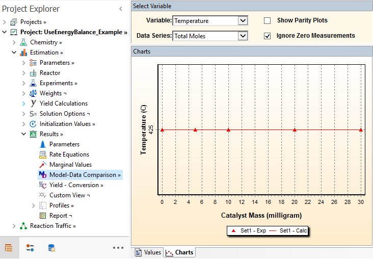
After running the project, you may check the temperature profile in the
Model Data Comparison node:
In the next step, we will enable the Energy Balance calculations.
Step2: Enabling Energy Balance with default options
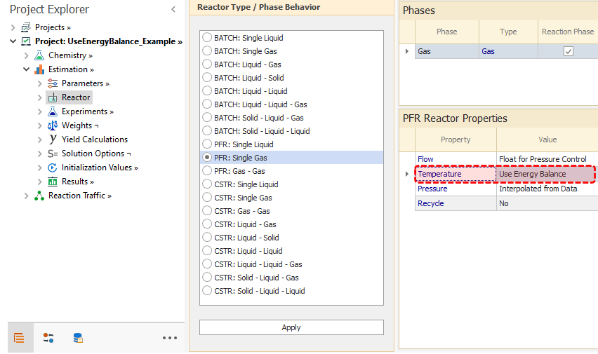
You may activate the Energy Balance model in the
Estimation → Reactor node by changing the option for Temperature to
Use Energy Balance as shown below:
For a Single Phase reactor (as in this example), the
Heat of Reaction node is also shown when Energy Balance is enabled:
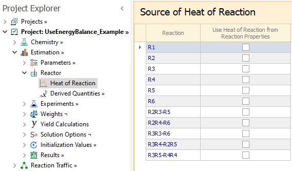
This node contains a list of included reactions in the project, and by default, all checkboxes are
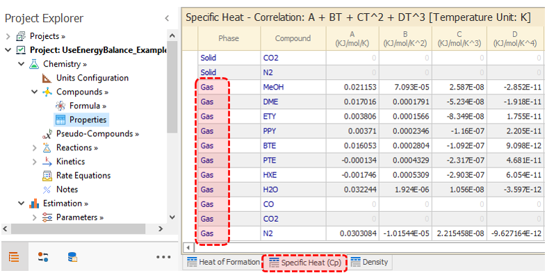
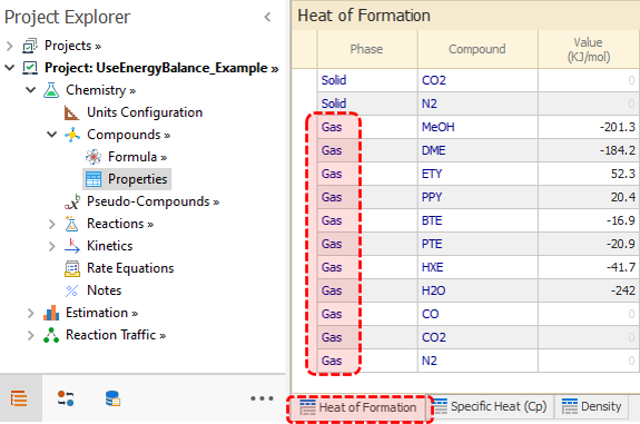
OFF. This means that the Heat of Reaction for all reactions will be calculated internally based on the Specific Heat and Heat of Formation provided in
Chemistry → Compounds → Properties node, as follows:
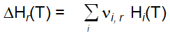
Where Heat of Reaction of reaction
r at a Temperature
T is obtained based on the compounds enthalpy
Hi(T), multiplied by the stoichiometric coefficients
vi,r.
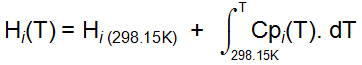
The compound enthalpy is obtained by the following integration:
where
Hi(298.15K) is the Heat of Formation at standard conditions (T=298.15K) and Cp is the molar specific heat.
Our example file has these properties already entered for the Gas phase:
If you now look at the
Solver → CheckModel view, you will see that there are warnings about the missing Cp data for CO, CO2 and USY in gas phase. In this example, these compounds are neither fed nor produced by any reaction, so it is not necessary to enter these values. Nevertheless, we always recommend that you use the Checkmodel feature to verify the consistency of the model.
You may
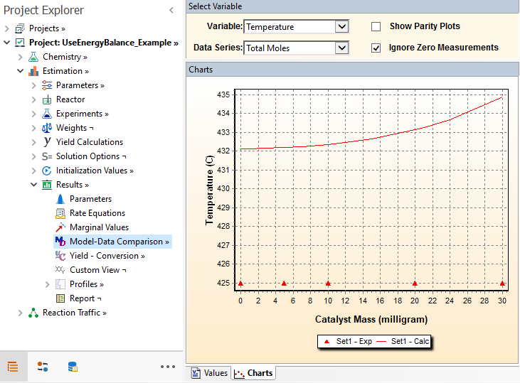
Run the project and view the Temperature profile in the
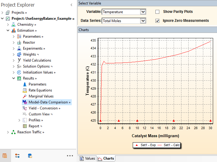
Model Data Comparison node:
As shown in the chart, the entry temperature is same as the experimental measurement at the inlet, which is 425C. As the reaction proceeds, the temperature profile evolves in response to the heat released or consumed by the reactions.
The stiff initial increase of Temperature is mostly due to the
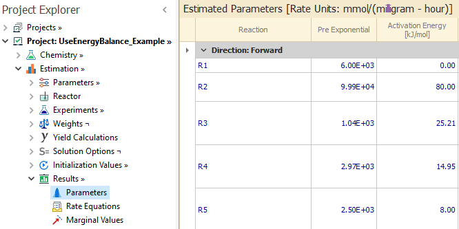
R1: 2 MeOH <--> DME + H2O reaction. This reaction is very fast and approaches equilibrium quickly in the early stage of the reactor. REX also indicates the presence of such fast reversible reactions by marking them with a light green double arrow in the
Results → Parameters node, as shown below:
Step 3: Energy Balance with Equilibrated Reactions
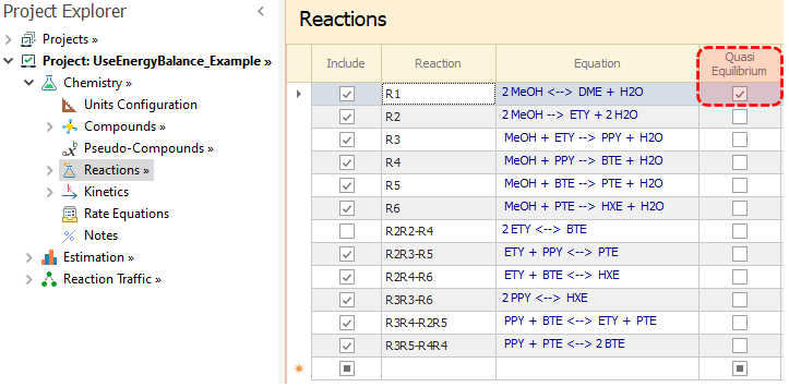
We have seen that reaction
R1 is fast enough to mark it as a
Quasi-Equilibrium in
Reactions node:
After running again, we inspect the resulting Temperature profile:
Please note that the calculated inlet Temperature(at Catalyst Mass= 0) is
not the same as the experimental value of 425C. Since
R1 is now equilibriated, REX calculates the composition changes for DME, MeOH and H2O due to equilibrium. The resulting temperature rise due to instantaneous equilibrium is also calculated. These equilibriated values of composition and temperature are then directly assigned to the reactor entry. Thus, the calculated values shown at the inlet condition are different from the experimental values. The composition adjustment caused by equilibrated reactions is also explained in this
Example.
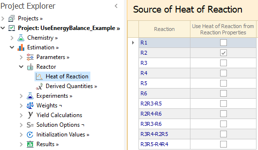
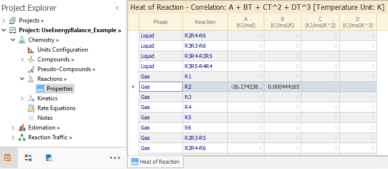
Step 4: Use Heat of reaction from Reaction Properties
By default, REX internally calculates the heat of reaction based on heat of formation and specific heat of compounds. In some cases, you may wish to directly provide the heat of reaction and force REX to use the provided values. For single phase reactors, it is possible to do this. For example, in order to use Heat of Reaction values for reaction
R2, please mark this reaction in the
Heat of Reaction node:
That implies that the heat of reaction for R2 will now be calculated based on the values loaded in the
Chemistry → Reactions → Properties node:
For all other reactions, the heat of reaction will still be calculated based on the Specific Heat and Heat of Formation entered in the
Chemistry → Compounds → Properties node.
Step 5: Energy Balance in Mode Optimization
We now illustrate the energy balance features in optimization mode.
First, please go to the
Project Name node and execute the
Mode → Change to Optimization action. You will now find an optimization case loaded in the
Design Values node. The conditions for the case are similar to what we have seen in Estimation mode. In the
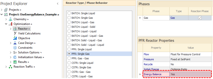
Reactor node, Energy Balance is enabled as shown in the image below:
As always, Temperature values and bounds are specified in the
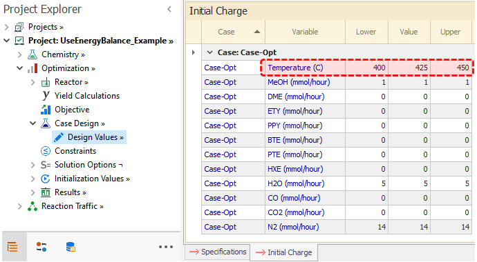
Design Values → Specifications tab. The bounds are applied for all temperature values along the reactor. When Energy Balance is enabled, REX also allows you to independently specify the Temperature values and bounds for the feed. This is done in the
Design Values → Initial Charge tab.
For the PFR reactor in this example, the Temperature variable in the
Initial Charge tab refers exclusively to the temperature of the entry feed. This allows you to try different scenarios. For example, you may fix the feed Temperature while allowing the Temperature profile to stay within some bounds along the reactor.
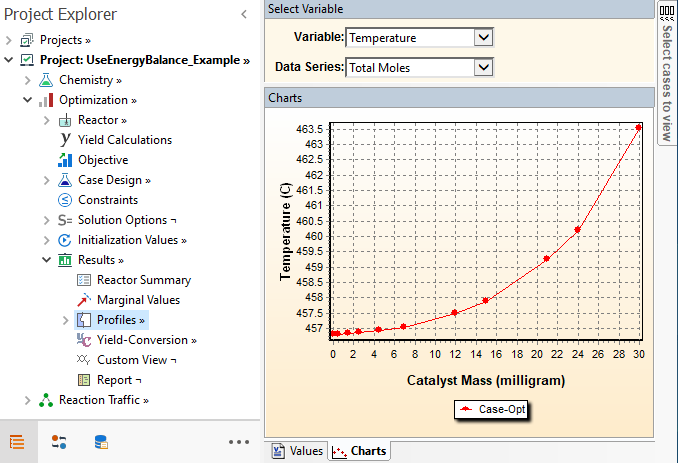
After running the project, you may see the temperature in the
Results → Profiles node:
As we saw in Step 3, note that the temperature in the reactor inlet is about 456C, which is higher than the bound enforced in the
Design Values → Initial Charge tab. This is because when we have a reaction marked as
Quasi-Equilibrium, we allow for the temperature to be re-calculated to satisfy equilibrium conditions independent of the bounds. This is similar to what we showed for the estimation example in step 3. Compounds belonging to the equilibrated reaction R1 (DME, MeOH and H2O) are also adjusted from the values provided in the
Initial Charge. The composition adjustment caused by equilibrated reactions is also explained in this
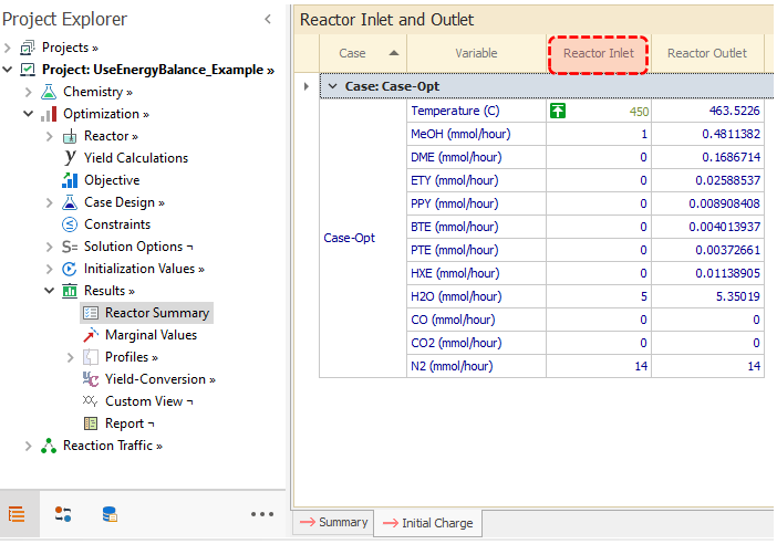
Example. However, the non-equilibrated feed temperature and compositions are still reported in the
Initial Charge tab of the
Results → Reactor Summary node: